
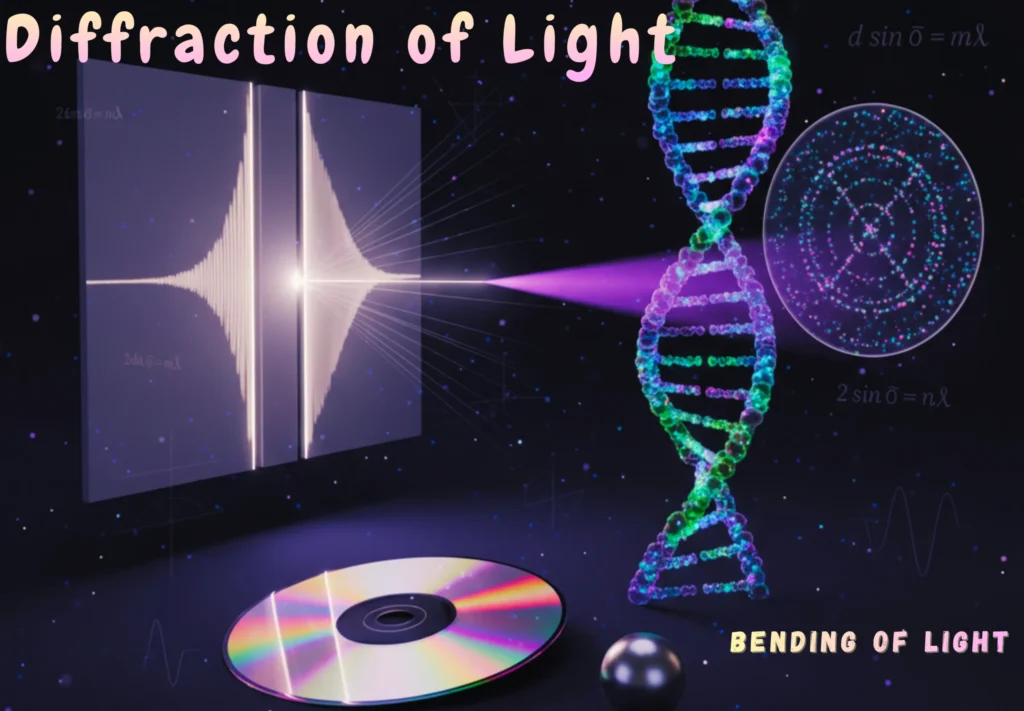
The study of diffraction of light has shaped our understanding of both optics and modern physics.
Table of Contents
Introduction
Have you ever wondered why shadows are not always perfectly sharp? Or did you ever notice how light peeks around corners, or how a CD reflects rainbow colours? Believe it or not, that is light showing off one of its coolest tricks — diffraction.
From colourful CDs to cutting-edge research, diffraction is more than just a quirky wave behaviour. It is a window into the unseen. It tells us that:
- Light is not just a particle; it is a wave too.
- Even the tiniest waves leave fingerprints you can read.
- The patterns it creates can reveal the structure of matter itself.
Here is a look at how this phenomenon is demonstrated, modelled, and ultimately utilised to peer into the structure of matter.
What is Diffraction of Light?
It can be defined as:
“The bending and spreading of light waves when they encounter an obstacle or pass through a narrow opening”.
Contrary to the idea that light travels strictly in straight lines, experimental observations confirm that it bends.
Light usually travels in straight lines; however, under certain conditions, it can bend around objects or edges. This bending of light is called diffraction.
Note
- Diffraction occurs because of interference between light waves coming from different parts of the same wavefront.
- It becomes noticeable when the wavelength of light (λ) is comparable to the size of the obstacle or slit.
Experimental Evidence of Diffraction
Scientists first discovered the bending of light through several simple experiments.
1. Young’s Double Slit Experiment
In Young’s double slit experiment, a bright central fringe appears on the screen.
- If light only travelled in straight lines, this central area should have been dark (the shadow region between two slits).
- However, the bright central region shows that light bends and overlaps, proving that diffraction and interference occur.
2. The Steel Ball Experiment
A small, smooth steel ball (about 3 mm in diameter) is illuminated by a point source of light.
- The shadow of the ball on a screen is not completely dark—it has a bright spot in the centre.
- According to Huygen’s Principle, every point on the edge of the ball acts as a new source of wavelets, which overlap and illuminate the centre of the shadow.
These observations clearly show that light can bend around obstacles instead of only traveling in straight lines.
Activity
Try this simple activity:
- Hold two fingers close together to form a narrow slit.
- Look at a light bulb through the slit.
You shall see a pattern of light and dark bands. It is an everyday example of diffraction and interference!
Diffraction Due to a Narrow Slit
Consider the following schematic to study the bendng of light through a narrow slit:
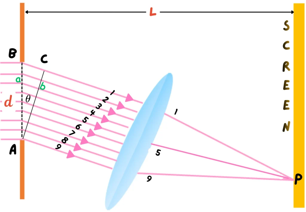
- A slit AB of width d is illuminated by a parallel beam of monochromatic light.
- A screen S is placed parallel to the slit.
- Each point on the slit behaves like a small source of light waves, sending out secondary wavelets toward the screen.
- These wavelets overlap and interfere, forming a diffraction pattern.
Interference Analysis
To understand how the pattern forms:
- Imagine several rays passing through the slit (many more than the nine drawn here).
- Rays that start in phase (like ray 1 and ray 5) will have a path difference when they reach a point on the screen.
- If that difference equals
 , they interfere destructively, producing a dark region.
 - The path difference between the rays is given by:
 , they interfere destructively, producing a dark region.
Conditions for Minima (Dark Regions)
Destructive interference occurs when the waves cancel each other.
1st Order Minima
The first minimum appears when:

Higher-Order Minima
For higher-order dark regions:

Where m = ±1, ±2, ±3, …
The Diffraction Pattern
The pattern formed on the screen consists of:
- A bright central region (central maximum).
- Alternating dark and bright fringes on either side.
- Bright regions appear between any two consecutive minima.
This characteristic pattern beautifully demonstrates how wave interference creates diffraction effects.
What Is a Diffraction Grating?
It can be defined as:
“A flat surface (often glass) with many fine, parallel lines ruled closely together”.
The important things to notice here are:
- The spaces between the lines act as tiny slits.
- A grating typically has 400 to 5000 lines per centimetre.
- When light passes through it, each slit produces secondary wavelets, creating multiple interference patterns.
Grating Element and Path Difference
The distance between two consecutive slits is called the grating element (d).
- It is calculated as
 , where L is the grating’s total length and N is the number of lines.
 - When monochromatic light hits the grating, the path difference between rays from adjacent slits is:
 , where L is the grating’s total length and N is the number of lines.
Constructive Interference (Bright Regions)
For bright fringes (constructive interference):

Substituting the value of ab:

Here, n is the order of the diffraction (n = 0, ±1, ±2, …).
Orders of Diffraction
As stated earlier, n is an integer value. Hence, for:
Zero Order ( )
)
 )
)Light travels straight through ( ), producing the brightest central image.
First Order ( )
)
 )
)Occurs when on both sides of the central image.
Higher Orders ( )
)
 )
)Additional bright images appear at larger angles, with dark spaces in between.
The Bending of White Light
When white light (which contains multiple wavelengths) passes through a grating:
- Each colour is diffracted at a different angle.
- This creates spectra of colours, especially visible in higher diffraction orders.
Fun Fact
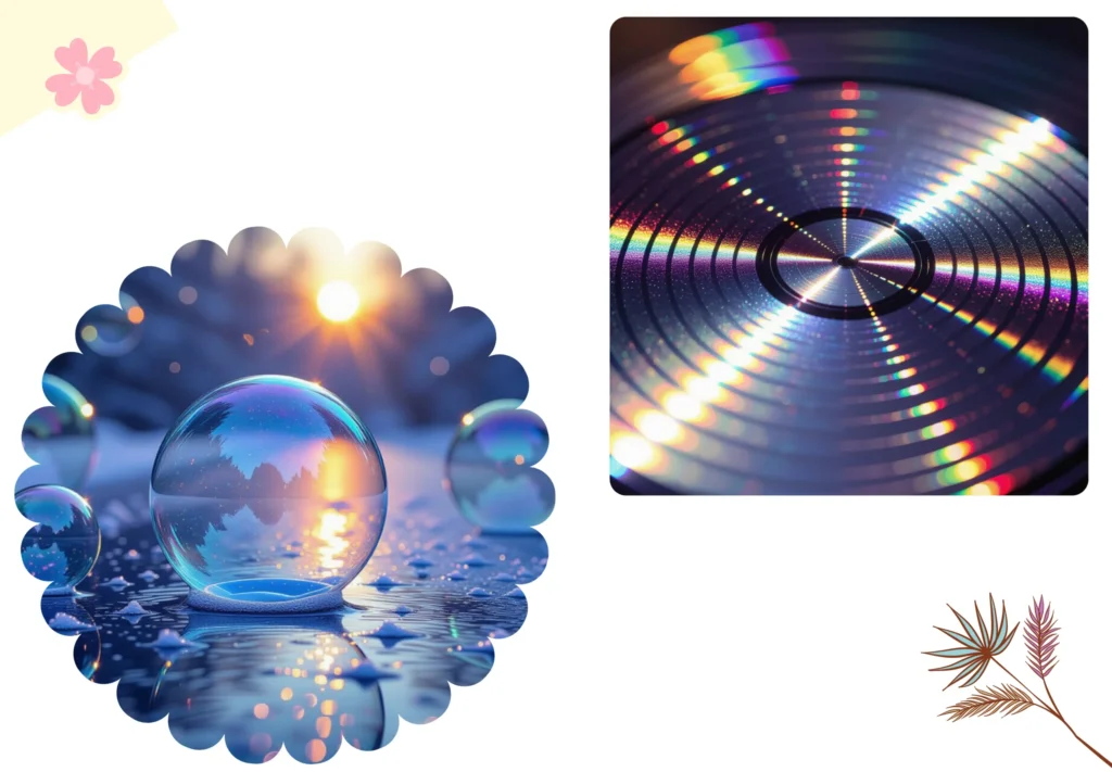
The fine grooves on a compact disc (CD) act like a diffraction grating. They produce colourful reflections when viewed under white light!
Diffraction of X-Rays by Crystals
X-rays have very short wavelengths, which are about 10⁻¹⁰ meters.
Ordinary diffraction gratings cannot be used because their spacing (~10⁻⁶ m) is too large.
However, crystals naturally contain regular arrays of atoms spaced at about 10⁻¹⁰ m, making them perfect natural gratings for X-rays.
This validates why crystals are used for the diffraction of X-rays.
Bragg’s Law
The diffraction in crystals was first discovered by W.H. Bragg and W.L. Bragg in 1914. They discovered that crystals reflect X-rays at specific angles and produce diffraction patterns.
The law states that:
“Constructive interference occurs when  ”.
”.
Where d is the spacing between crystal planes.
It explains how X-rays reflect from atomic layers in crystals.
Crystal Reflection
Consider a set of parallel crystal planes separated by a distance d‘.
- When X-rays hit the crystal at an angle
 , some waves reflect from the top plane, and others from deeper planes.
 - The extra distance travelled by the lower beam is

- For constructive interference (bright reflection), this path difference must equal an integer multiple of the wavelength:
 , some waves reflect from the top plane, and others from deeper planes.
This is known as Bragg’s Law.
Applications of Bragg’s Law
Bragg’s Law allows scientists to:
- Calculate the spacing between atomic layers in a crystal.
- Understand the structure of materials at the atomic level.
Some famous applications include:
- Determining the structure of haemoglobin, an essential protein in blood.
- Revealing the double helix structure of DNA, one of the greatest scientific discoveries of the 20th century.
Conclusion
Diffraction is a fascinating property of waves. It helps us understand the wave nature of light. It even explores atomic structures using X-rays. You can see it from simple classroom experiments to ground-breaking molecular discoveries.
It is not something you see every day, but once you know where to look, it is everywhere. It lets you explore how scientists discovered it, what it means, and how it even helps us uncover the secrets of DNA.
Frequently Asked Questions (FAQs)
What is the diffraction of light in simple terms?
It is the bending and spreading of light waves when they pass through a narrow opening or around an obstacle. It shows that light behaves like a wave, not just a particle.
What causes light to bend during diffraction?
Light bends because different parts of a wavefront interfere with each other. The bending becomes noticeable when the wavelength of light is similar to the size of the slit or obstacle.
What are some real-life examples of diffraction?
Examples include the colourful patterns on CDs and DVDs, the fuzzy edges of shadows, and the rainbow-like effects seen when light passes through fine meshes or tiny openings.
What did Young’s Double Slit Experiment prove?
Young’s Double Slit Experiment proved that light behaves as a wave by showing interference patterns—alternating bright and dark fringes—on a screen when light passes through two narrow slits.
What is the condition for minima in single-slit diffraction?
Dark regions or minima occur when the path difference between light waves equals an integer multiple of the wavelength:
Where m = ±1, ±2, ±3, …
What is a diffraction grating used for?
It is used to separate light into its component wavelengths. It has thousands of fine parallel lines that act as multiple slits, creating precise and vivid interference patterns.
How is the diffraction of white light different from monochromatic light?
When white light is diffracted, each colour bends at a different angle due to varying wavelengths, forming a visible spectrum. Monochromatic light, however, produces a single-color pattern.
What is Bragg’s Law in X-ray diffraction?
Bragg’s Law states that constructive interference occurs when 2d sin θ = nλ, where d is the spacing between crystal planes. It explains how X-rays reflect from atomic layers in crystals.
Why are crystals used for X-ray diffraction?
Crystals have regularly spaced atomic planes with distances similar to X-ray wavelengths (~10⁻¹⁰ m), making them natural diffraction gratings for studying atomic structures.
What are the applications of diffraction in science?
It is used in spectroscopy, optical instruments, and crystallography. It helped reveal the structures of materials like haemoglobin and DNA, transforming modern science.