
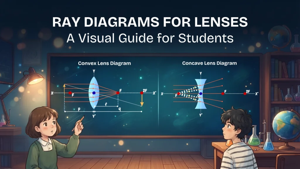
Ray diagrams for lenses may seem like a collection of diagrams that demands rote memorisation, but it goes beyond that.
Table of Contents
Introduction
Ray diagrams for lenses are one of the most important topics in high-school physics. They help us predict:
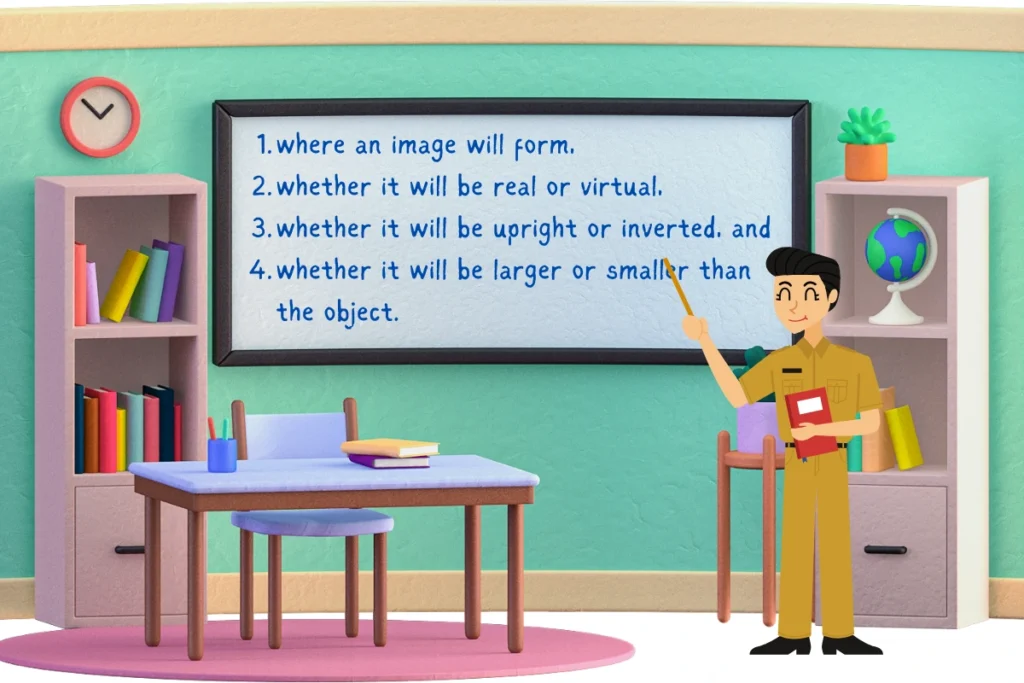
You only need to understand a few basic ray rules. Once you know those rules, the different image-formation diagrams follow logically.
What Is a Ray Diagram for Lenses?
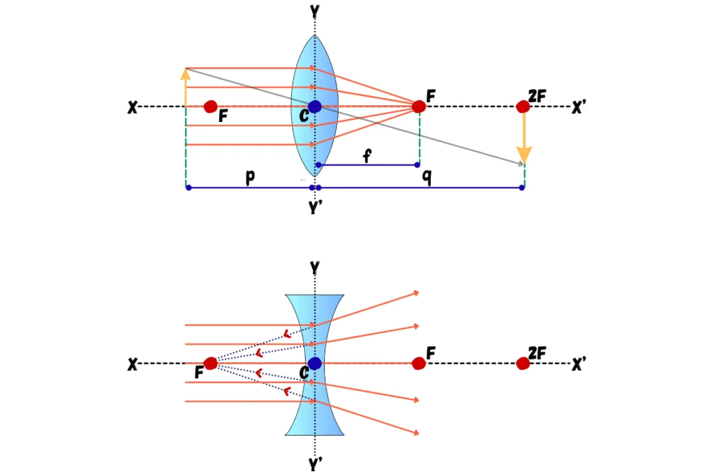
A ray diagram is a drawing that shows how selected rays of light travel through a lens and where they meet—or appear to meet—to form an image.
A basic lens diagram contains several important features (click here). The rays in a convex lens are converging, while in a concave lens they are diverging.
The 2 Main Types of Lenses
Before drawing any ray diagram, identify the type of lens.
| Convex Lens | Concave Lens |
| A convex lens is thicker in the middle and thinner at the edges. | A concave lens is thinner in the middle and thicker at the edges. |
| It is also called a converging lens because parallel rays passing through it are refracted toward the principal axis and can meet at the focus. | It is also called a diverging lens because parallel rays passing through it spread apart. The rays appear to originate from a focal point on the same side of the lens as the object. |
| A convex lens can produce: real or virtual images;inverted or upright images;enlarged, diminished, or same-sized images. | For a normal object, a concave lens produces an image that is: virtual; upright; diminished. |
The 3 Principal Rays Used in Lens Ray Diagrams
Not every ray coming from an object needs to be traced.
A few carefully selected rays are enough to locate the image position. In fact, 2 principal rays are generally sufficient for the task.
The following 3 rays are the most useful. These rays are either refracted (Ray 1, Ray 3) or remain unchanged (Ray 2).
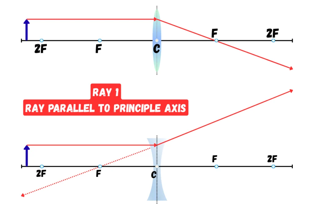
Ray 1: Ray Parallel to Principle Axis
A ray travelling parallel to the principal axis behaves differently for the two types of lenses.
| Convex Lens | Concave Lens |
| A ray parallel to the principal axis is refracted through the principal focus on the opposite side. | A ray parallel to the principal axis is refracted outward. Its backward extension appears to pass through the focus on the same side as the object. |
| Parallel → Focus | Parallel → Appears to come from Focus |
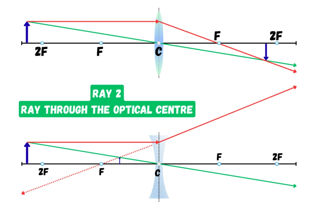
Ray 2: Ray through the Optical Centre
Any ray that passes through the optical centre of a thin lens is treated as an undeviated ray. This is the easiest ray to draw because it simply continues in a straight line.
This rule applies to both convex and concave lenses.
Ray 3: Ray through the Focus
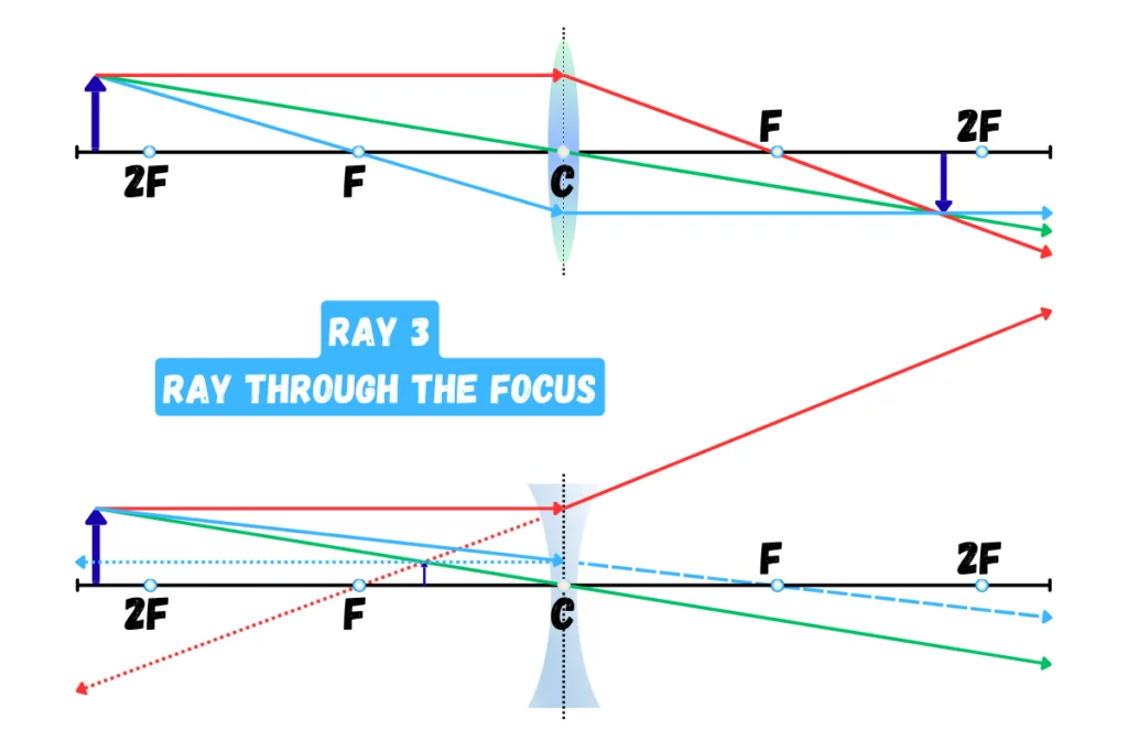
For a convex lens, a ray directed through the focus before reaching the lens emerges parallel to the principal axis.
So:
Through Focus → Parallel
For a concave lens, the corresponding construction uses a ray directed toward the focal point on the opposite side; after refraction, it emerges parallel to the principal axis.
Why Do Ray 3 Paths Differ Between Lenses?
The directional behaviour of Ray 3 differs because of the physical geometry of each lens type. A lens alters light paths based on its structural curvature. It determines whether an incident ray must interact with the near or far focal point before it emerge parallel to the principal axis.
| Features / Details | Convex Lens | Concave Lens |
| Optical Behaviour | Convergent: Bends light inward toward the principal axis | Divergent: Bends light outward away from the principal axis. |
| Condition for Parallel Emergence | The ray must pass directly through the focal point before entering the lens. The lens then bends the path outward to flatten it parallel to the axis. | The ray must aim straight toward the focal point located behind the lens. The lens refracts the path inward just enough to flatten it parallel to the axis. |
| Focal Point Reference | Near Focal Point (Same side as the object) | Far Focal Point (Opposite side of the object) |
How to Draw a Lens Ray Diagram
The general process is simple.
Step 1: Draw the principal axis
Draw a horizontal straight line.
Step 2: Draw the lens
Place the convex or concave lens on the principal axis.
Step 3: Mark F and 2F
Mark the focal point and the 2F position on the appropriate side or sides of the lens.
Step 4: Draw the object
Place the object at the position specified in the question.
Step 5: Select two principal rays
Choose two easy-to-draw rays (preferably Ray 1, Ray 2).
Step 6: Trace the intersection of rays
Use the rules described above to see where the two rays intersect.
Step 7: Locate the image
The point where the refracted rays meet gives the image position (intersection point as a head).
If the rays do not actually meet but their backward extensions meet, the image is virtual.
(Look the images above for clarity.)
Convex Lens Ray Diagrams
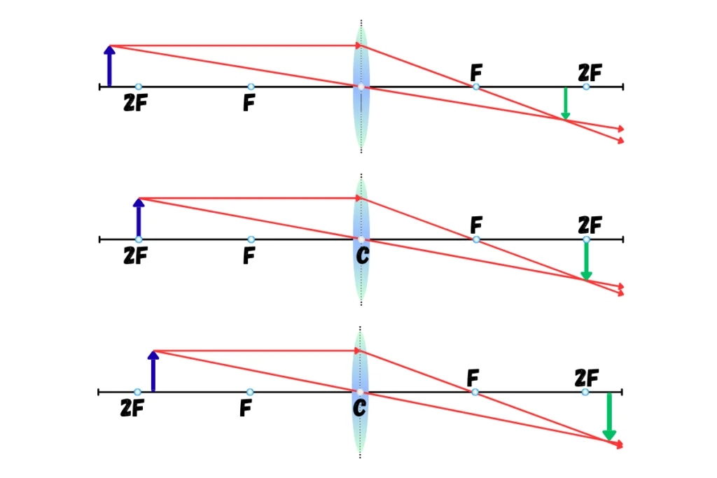
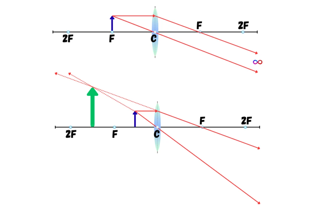
A convex lens has 5 standard object positions that students commonly study. The important thing is to learn what happens as the object moves relative to F and 2F.
This relative movement of object and image takes place as follows:
- Object: Beyond 2F → At 2F → Between 2F and F → At F → Between F and the Lens
- Image: Between F and 2F → At 2F → Beyond 2F → At ∞ → same side of the lens as the object
Convex Lens Ray Diagrams | 3/5 Standard Object Positions
Convex Lens Ray Diagrams | 2/5 Standard Object Positions
Convex Lens: Complete Image-Formation Table
| Object Position | Image Position | Nature | Size |
|---|---|---|---|
| Beyond 2F | Between F and 2F | Real, inverted | Smaller |
| At 2F | At 2F | Real, inverted | Same |
| Between F and 2F | Beyond 2F | Real, inverted | Larger |
| At F | At infinity | No finite screen image | — |
| Between F and lens | Same side of lens | Virtual, upright | Larger |
Concave Lens Ray Diagram
The concave lens is much easier to remember. It is a diverging lens, so its refracted rays spread apart.
When the rays are extended backward, they appear to meet at a point on the same side of the lens as the object.
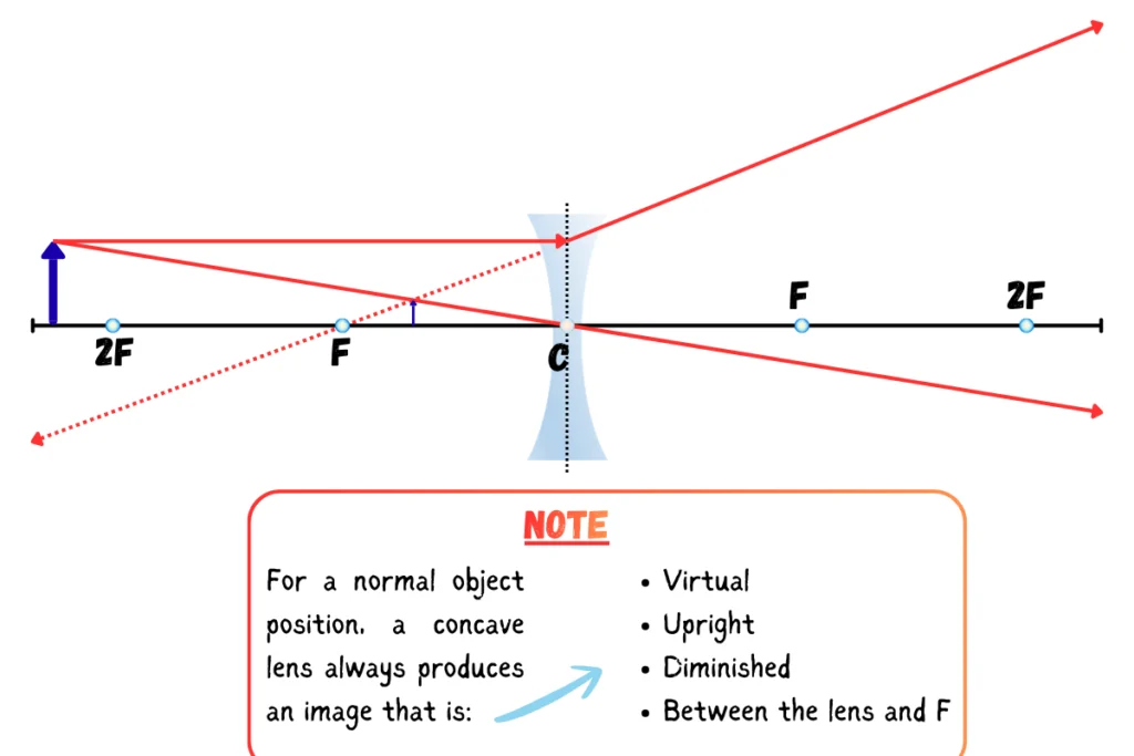
Unlike a convex lens, you do not need five different object-position cases for the standard single-lens image formation result.
Convex vs Concave Lens | Quick Comparison
| Feature | Convex Lens | Concave Lens |
| Shape | Thicker at centre | Thinner at centre |
| Other name | Converging lens | Diverging lens |
| Parallel rays | Converge | Diverge |
| Real image possible? | Yes | No, for the standard single-lens case |
| Virtual image possible? | Yes | Yes |
| Upright image possible? | Yes | Yes |
| Inverted image possible? | Yes | No, for the standard single-lens case |
| Enlarged image possible? | Yes | No |
| Diminished image possible? | Yes | Yes |
How to Solve Lens Ray-Diagram Questions
Not every exam question gives you a lens, object, and complete diagram. We can divide lens problems into 3 useful types.
This is where lens questions become more interesting.
Type 1: Lens and Object Position Are Given
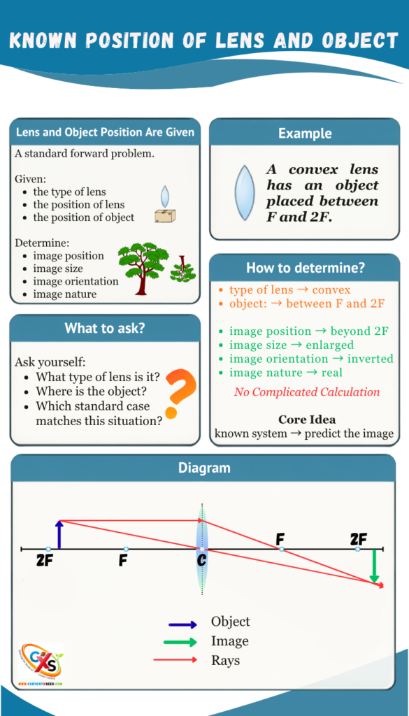
Type 2: Object and Image Positions Are Given
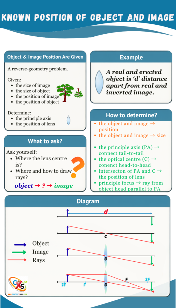
Type 3: Numerical Lens Problems
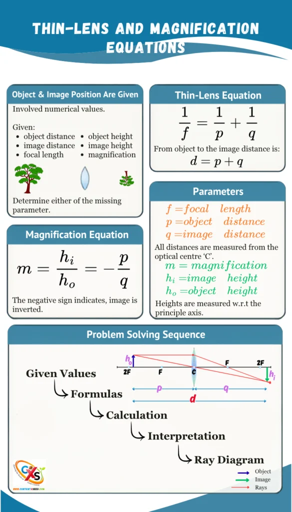
A Simple Decision Process for Exam Questions
When you see a lens question, do not immediately start drawing.
Ask these questions in order.
Question 1: What type of lens is it?
Convex or concave?
Question 2: Where is the object?
- beyond 2F
- at 2F
- between F and 2F
- at F
- between F and the lens
Question 3: What kind of problem is this?
- a standard diagram
- a reverse-geometry problem
- a numerical problem
Question 4: What information can I infer?
- image position
- image nature
- orientation
- size
- focal length
- object distance
- image distance
- magnification
Question 5: Which two rays should I draw?
Choose the simplest principal rays.
Question 6: Do the results agree?
Your diagram and your mathematical result should tell the same physical story.
Common Mistakes in Lens Ray Diagrams
Mistake 1: Memorising diagrams without understanding the rays
Mistake 2: Drawing too many rays
Mistake 3: Forgetting that virtual rays need backward extensions
Mistake 4: Confusing upright with real
Mistake 5: Treating magnification as just a number
The Golden Rule
Convex Lens: object position determines the image.
Concave Lens: the standard image is always virtual, upright, and diminished.
Conclusion
Ray diagrams for lenses are much easier when you stop treating them as pictures to memorise.
Instead, think of every problem as a small optical system.
- First identify the lens.
- Then identify the object position.
- Next, apply the principal-ray rules.
- Finally, determine the image parameters like:
- position
- nature
- orientation
- size
For numerical questions, use the lens formula and magnification equation to connect the mathematical information with the physical picture.
When a question gives you incomplete information, do not panic. Ask what part of the optical system is already known and what part needs to be reconstructed.
That is the real skill behind lens ray diagrams:
You are not memorising a collection of diagrams. You are learning the rules that generate them.
Once those rules become familiar, even unfamiliar ray-diagram questions become much easier to solve.
Frequently Asked Questions
What is a ray diagram for a lens?
A ray diagram is a graphical representation of how selected light rays travel through a lens and form an image.
How many rays are needed to draw a lens ray diagram?
Usually, two suitable principal rays are enough to locate the image. A third ray can be added to check whether the construction is correct.
What are the three principal rays for a convex lens?
The most commonly used rays are:
- A ray parallel to the principal axis, which passes through the focus after refraction.
- A ray through the optical centre, which continues approximately undeviated.
- A ray passing through the focus, which emerges parallel to the principal axis.
What image does a concave lens form?
It normally forms a virtual, upright, and diminished image between the lens and its focus.
What happens when an object is placed at F of a convex lens?
The refracted rays become parallel, so the image is formed at infinity. A sharp image cannot be obtained on a screen at a finite distance.
When does a convex lens form a virtual image?
When the object is placed between the lens and its focal point.
Can a convex lens form an enlarged image?
Yes. It can form an enlarged real image when the object is between F and 2F, and an enlarged virtual image when the object is inside F.
What does negative magnification mean?
Using the signed magnification convention

Here, the negative magnification indicates an inverted image.